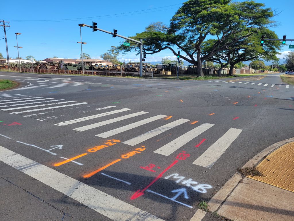
Locating underground utilities has been described as both an art and a science. We hope to help you understand the science aspect of our process.
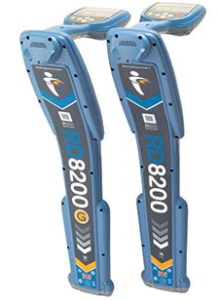 We currently use the RD Radiodetection and Vivax Metrotech cable-pipe locator for all our utility locating needs. This equipment, which is widely recognized as the industry standard because it maintains the highest locate performance, contains multiple locate modes and is easy to use. The science of cable and pipe locating is based on the principal that a current flowing along a conductor creates a magnetic field, and that magnetic field or signal, which is either passive or active in nature, can be detected via a receiver.
A passive signal is one that is naturally occurring around a conductor, or in this case an underground utility. Some examples of passive signals include the following: A. Current flowing in an electric supply cable. B. Earth return current from power systems that use metal pipes or cable sheaths as a convenient conductor. C. Radio frequency currents from very low frequency (VLF) radio transmissions that have penetrated the ground and flow along a buried utility. A passive sweep is performed to search for inaccessible, abandoned or unknown utilities using only a receiver. To perform a passive sweep, a survey grid is traversed in “power” mode, with the receiver blade in line with the direction of movement and at right angles to any utilities that may be crossed. When the receiver indicates the presence of a utility, it is pinpointed, traced and marked. The sweep is then continued until all detected utilities have been marked and the entire grid has been traversed in both directions. After completing the sweep, the entire process is repeated in “radio” mode to search for utilities that radiate VLF radio signals.
Passive signals enable utilities to be located, but not identified, because the same signal may appear on multiple utilities within the grid. To solve this problem, an active signal must be applied to each individual utility line.
An active signal is one that is intentionally generated by a transmitter. In this mode, the signal can be applied directly to the utility via direct connection or induction. This enables utilities to be identified, traced and their depth determined with a receiver. Direct connection involves plugging a connection cable into a transmitter output socket and connecting directly to the target line. This can be accomplished with connection leads or with a transmitter clamp. Connection leads are generally used to apply a signal to metallic conduits, sight lighting structures and metallic pipes. This is the preferred method for locating secondary electric, water and gas. 
Many electric, telephone and cable lines are housed within plastic conduits or buried into the ground without protection. In addition, directly connecting to these lines is usually too risky or forbidden. In such instances, a transmitter clamp is used to apply a signal to the cable without interrupting service to the line. The clamp is easy to apply, but the signal may not travel as far as it does with connection leads, and works best if the target line is grounded at each end. This is the method of choice for locating primary electric, telephone and cable lines.
If an active signal cannot be applied to a line because it is inaccessible, an induction sweep must be performed. The transmitter contains an antenna, that when placed on the ground directly on top of a utility line, can induce a signal into it. The advantage of using induction is that a signal can be applied without access to the line and it is very quick and easy to use.
 The disadvantages are that induction efficiency is poor on deep targets, it is only useful at depths down to 6 feet and the signal can induce into lines other than the target. In addition, signal strength is often lost in the surrounding soil, the signal is shielded by reinforced concrete and a signal will not apply to a well-insulated line unless it is effectively grounded at each end. Despite its shortcomings, an induction sweep can sometimes successfully locate unknown or abandoned utilities when GPR results are inconclusive.
An active signal cannot be applied to non-conductive (non-metallic) utility, plastic sewer lines and fiber optic lines. To combat this, a detectable duct rod or self-contained transmitting sonde must be inserted into the line via a manhole, hand hole, cleanout or catch basin. The disadvantages of this method are that some nonmetallic utility lines do not have access points or might be obstructed by detritus. Nonetheless, this is the best method for locating fiber optics, future use lines, sanitary sewer and storm sewer.
When it comes to Ground Penetrating Radar (GPR) quite often, anomalies, non-metallic, inaccessible, unknown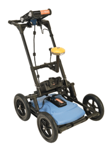 objects or abandoned utilities cannot be located with traditional cable and pipe locators. When this occurs, Ground Penetrating Radar (GPR) must be used in conjunction. GPR is a non-invasive, non-destructive geophysical surveying technique that is used to produce a cross-sectional view of objects embedded within the subsurface. We currently use the Radiodetection RD-1100-GPR to perform our ground radar surveys. This piece of equipment, which is manufactured by Radiodetection Systems Incorporated, is their latest data acquisition system and the industry’s number one choice for data accuracy and versatility.
All GPR units consist of three main components: a power supply, control unit and antenna. To understand how GPR works, we must first understand the performance of what a scan is. A scan is performed by moving the antenna across the surface linearly to create a series of electromagnetic pulses over a given area. During a scan, the control unit produces and regulates a pulse of radar energy, which is amplified and transmitted into the subsurface at a specific frequency by the antenna. Antenna frequency is inversely proportional to penetration depth, which makes antenna selection the most important step in the survey design process.
During a scan, the control unit records the strength and time required for the return of any reflected energy. Reflections are produced in the data screen profile (on the control unit) whenever the energy pulse enters and exits contrasting subsurface materials. The way it responds to each material is determined by two physical properties; dielectric constant and electrical conductivity. Since the GPR emits electromagnetic energy, it is subject to attenuation (natural absorption) as it moves through a material. Energy moving through resistive (less conductive) materials such as dry sand, ice or dry concrete will penetrate much further than energy moving through absorptive (more conductive) materials such as salt water or wet concrete. As a result, the greater the contrast in electrical conductivity between the material one is scanning through and the target one is searching for, the brighter the reflection; high conductive materials such as metals produce the brightest reflections.
 To gather, organize and present the data, a series of scans are performed within an orthogonal survey grid. At the end of each scan, the data screen profile is reviewed for the presence of hyperbolic targets. If present, the antenna is moved backward to place a cursor (which depicts the center of the antenna) on the center of the targets. The location and depth of the targets are then marked on the surface with chalk, paint and/or flags. Once the entire survey grid has been scanned, the marks are reviewed to search for patterns similar to that of the desired targets. Any marks that run in straight line and whose hyperbolas appear to be highly conductive metal targets are then connected, thereby displaying the location and depth of the pipe.
Results..
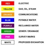
Underground utilities were marked on the ground with paint and/or flags using the standard color codes. Electric lines and ground wires were marked with red, water lines with blue, gas lines in yellow, cable/phone in orange and unknown/survey lines with pink. Please note that due to high levels of water in the ground, readings from GPR – Ground Radar and electromagnetic locators should be given plus or minus (+/-) One-foot (1′) variance.
